Home
› Wiring Gfci Schematic : GFCI Outlet Wiring Diagram | House Electrical Wiring Diagram / Below mentioned wiring diagram shows a single gfci outlet connected with the multiple outlets.
Wiring Gfci Schematic : GFCI Outlet Wiring Diagram | House Electrical Wiring Diagram / Below mentioned wiring diagram shows a single gfci outlet connected with the multiple outlets.
Wiring Gfci Schematic : GFCI Outlet Wiring Diagram | House Electrical Wiring Diagram / Below mentioned wiring diagram shows a single gfci outlet connected with the multiple outlets.. Wiring a gfci outlet with diagrams. 20 amp 2 pole gfci breaker wiring how to wire a diagram for circuit full the river pool is rooted in italian hot tub balboa application notes diagrams do it 240 volt page 1 square d homeline 50 siemens omegadiamond breakers 35 220v w209 240v 89 ground fault interrupter interruptors jeep 60 outlet installation 3 phase heating with single main. Click set line jumps in the smartpanel to show or conceal line hops at crossover points. The hot source is spliced to the line terminal on the receptacle and to one terminal on the light switch. Gfci outlet wiring diagram :
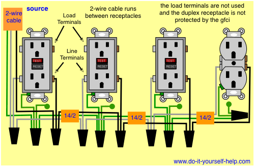
Protected receptacle(s) will be connected to the gfci load side as shown below. Wiring a gfci receptacle is a little more complicated than hooking up a regular outlet but easily learned once explained. Gfci outlet wiring diagram : Wiring a gfci outlet with a light switch diagram print the wiring diagram off plus use highlighters in order to trace the signal. A wiring diagram is a streamlined traditional photographic depiction of an electrical circuit.
electrical - Wiring diagram/configuration for 8 outlets ... from i.stack.imgur.com It shows the parts of the circuit as simplified shapes, and the power and signal links between the devices. Wiring a gfci outlet with diagrams pro tool reviews. A technician will answer you now! Schematic and actual wiring diagram is also provided. You'll have to use that single gfci as the source and then connecting the rest of the outlets using the same load and line terminals. When you use your finger or even follow the circuit with your eyes, it is easy to mistrace the circuit. It reveals the parts of the circuit as simplified forms, as well as the power and signal links in between the tools. Take a look at the control schematic 4.
A wiring diagram is a streamlined traditional photographic depiction of an electrical circuit.
Protected receptacle(s) will be connected to the gfci load side as shown below. You'll have to use that single gfci as the source and then connecting the rest of the outlets using the same load and line terminals. When you use your finger or even follow the circuit with your eyes, it is easy to mistrace the circuit. This device can be used for ground fault protection near water sources such as in a kitchen or bathroom where space is a minimum and both devices are needed. Almost everyone has heard of a gfci (ground fault circuit interrupter). 20 amp 2 pole gfci breaker wiring how to wire a diagram for circuit full the river pool is rooted in italian hot tub balboa application notes diagrams do it 240 volt page 1 square d homeline 50 siemens omegadiamond breakers 35 220v w209 240v 89 ground fault interrupter interruptors jeep 60 outlet installation 3 phase heating with single main. Print the cabling diagram off and use highlighters to be able to trace the circuit. Find gfci outlets now at theanswerhub.com! To properly wire gfci, or ground fault circuit interrupter receptacles, turn off the power to the circuit you're working on and unscrew the cover plate on the outlet box. In the second diagram, the light switch is connected to the line terminals of gfci. It shows the components of the circuit as simplified shapes, and the gift and signal connections in the middle of the devices. Gfci wiring method article shows outlet wiring a gfi using the tailed method. It reveals the parts of the circuit as simplified forms, as well as the power and signal links in between the tools.
For more on the basics of a gfci see our article on ground fault. You can also learn about wiring gfci outlets in the following 7 steps. Click the icons below to get our nec ® compliant electrical calc elite or electric toolkit, available for android and ios. The gfci should stay latched when power is removed and relit if you dont trust the gfci latched they make gfci breakers to protect the whole circuit from the breaker panel. You can wire a single gfci with multiple outlets using the 2 wires cables, multiple outlets, and gfci.
Wiring Diagrams for GFCI Outlets - Do-it-yourself-help.com from www.do-it-yourself-help.com Wiring a gfci outlet with a light switch in the first diagram, the single way switch and light bulb is connected to the load terminal of gfci. Use electrical wiring diagrams to assist in building or manufacturing the circuit or digital gadget. The three phase wiring for gfci or rcd (rccb) or rcbo wiring diagram shows the three lines (l1, l2 and l3) and neutral has been connected as input to the rccb from main board followed by mcb i.e. Gfci receptacle wiring diagram leviton 20 amp gfci wiring diagram credit: Gfci outlet wiring method this article and the electrical wiring diagram will show you how to install a gfi using the feed through method which will protect more than one outlet. A technician will answer you now! Ground fault circuit interrupter gfci is a device which secure person from electric shocks from faulty currents in the electrical devices we use in our daily lives. Questions answered every 9 seconds.
How to wire gfci outlets.
Wiring a gfci outlet with diagrams pro tool reviews. If you are replacing an existing gfci outlet with a new one we suggest that you read our page about replacing a gfci outlet. You can wire a single gfci with multiple outlets using the 2 wires cables, multiple outlets, and gfci. Wiring a gfci outlet with a light switch diagram print the wiring diagram off plus use highlighters in order to trace the signal. Questions answered every 9 seconds. 240v breaker wiring diagram page 1 line 17qq com. I am installing a used hot tub that has a seperate water heater. In the second diagram, the light switch is connected to the line terminals of gfci. Kitchen gfci wiring diagram gfci wiring diagram with the switch separate (with images … Wiring a gfci outlet and a light switch this diagram illustrates wiring a gfci receptacle and light switch in the same outlet box, a common arrangement in a bathroom with limited space. Split recepticle wiring electrical 101 kitchen receptacle circuits receptacles a gfci outlet with diagrams for switched wall load diagram mu full wire half hot 31 common household circuit wirings you multiple eight more s can t reset installing better vv 0423 1 2 switches existing counter light switch do it how to breaker outlets 3. Use electrical wiring diagrams to assist in building or manufacturing the circuit or digital gadget. Kitchen gfci wiring diagram gfci to gfci wiring diagram new 4 wire, volt wiring … credit:
A wiring diagram or schematic is a visual representation of the. It shows the parts of the circuit as simplified shapes, and the power and signal links between the devices. If you are replacing an existing gfci outlet with a new one we suggest that you read our page about replacing a gfci outlet. Split recepticle wiring electrical 101 kitchen receptacle circuits receptacles a gfci outlet with diagrams for switched wall load diagram mu full wire half hot 31 common household circuit wirings you multiple eight more s can t reset installing better vv 0423 1 2 switches existing counter light switch do it how to breaker outlets 3. Find gfci outlets now at theanswerhub.com!
basic electrical wiring: Sink Ground Fault Circuit Breaker ... from lh5.googleusercontent.com Questions answered every 9 seconds. Find gfci outlets now at theanswerhub.com! I am installing a used hot tub that has a seperate water heater. Wiring a gfci outlet with diagrams. How to wire gfci outlets. Variety of leviton gfci receptacle wiring diagram. Select program capacities to show the length of your cords or dimension of your component. To properly wire gfci, or ground fault circuit interrupter receptacles, turn off the power to the circuit you're working on and unscrew the cover plate on the outlet box.
Variety of leviton gfci receptacle wiring diagram.
Kitchen gfci wiring diagram gfci to gfci wiring diagram new 4 wire, volt wiring … credit: Gfci outlet wiring diagram : Then you just wire the circuit with the switch upstream of the outlet. Wiring a gfci outlet with diagrams pro tool reviews. Wiring a gfci outlet and a light switch this diagram illustrates wiring a gfci receptacle and light switch in the same outlet box, a common arrangement in a bathroom with limited space. Knowing you wount wire the switch on the live wire befor the gfci. If you are replacing an existing gfci outlet with a new one we suggest that you read our page about replacing a gfci outlet. Select program capacities to show the length of your cords or dimension of your component. The gfci should stay latched when power is removed and relit if you dont trust the gfci latched they make gfci breakers to protect the whole circuit from the breaker panel. This page contains wiring diagrams for a ground fault circuit interrupter (gfci) with a built in switch, often called a gfci outlet switch combo. Fully explained wiring instructions complete with a picture series of an installation and wiring diagrams can be found here in the gfi and light switch area here in this website. Wiring a gfci outlet with a light switch in the first diagram, the single way switch and light bulb is connected to the load terminal of gfci. It reveals the parts of the circuit as simplified forms, as well as the power and signal links in between the tools.